LRS2 Position Angle and Fiber Layout
The LRS2-B and LRS2-R IFU feeds are located 100" from each other in the direction 90 degrees from the altitude line at center of track. The short axes of the 12"x6" LRS2-B & LRS2-R IFUs are in the direction of the parallactic angle at center of track.
It is not possible at this time to specify an offset angle.
We have a script available to overlay the LRS2 IFU footprint on a PanSTARRS image for a given coordinate on the sky: https://github.com/sjanowiecki/HET_lrs2_finder.
Or you can use the older lrs2rho cgi script to determine the orientation of LRS2 on the sky for any coordinates. You can find more about the parallactic angle and how it is related to the DEC and optimal Az by looking at the HET Object Observability pages.
The World Coordinate System (WCS) has generally been determined although we continue to improve this. Please see the WCS page. for information on the WCS for the HET and see below for the LRS2 fiber layout information.
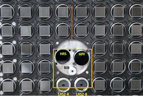
The image below show the layout of the LRS2 fiber bundles among the VIRUS units at the HET focus.
|
- Central part of the HET focal surface looking at the fiber feeds mounted in the input head mount plate (IHMP). A number of VIRUS IFUs are seen along with the feeds for LRS2-B and LRS2-R and the fiber feed for HPF. The BIB (boresight imaging bundle) is a small field imaging fiber bundle that defines a location on the IHMP so that the IHMP and the ACAM can be tied together and checked. The seat for the future HRS-2 feed is also indicated.
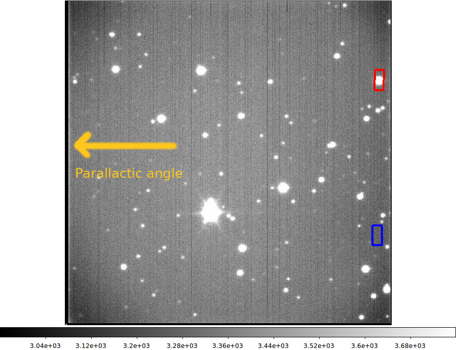
- The LRS2 IFUs have 6” x 12” format oriented as shown
- Parallactic angle (Tracker Y axis) is up in this figure, as indicated by the dark orange arrow; it is perpendicular to the long axis of the LRS2 IFUs
- The orange square indicates the field of view of the acquisition camera (ACAM) which is fed by a pick-off mirror that can be deployed in front of the IHMP.
- LRS2-B input head is mounted in IHMP slot 056 and the feed for LRS2-R in 066
To help the PI understand our setups and also to understand the results they get from the LRS2 we have provided (below) a list of X,Y pixel coordinates corresponding to the LRS2-B and LRS2-R IFU positions on the Acquisition Camera (ACQ or ACM or ACAM). These coordinates may be useful for the advanced user who wants to compare the ACQ camera setup images taken during the acquisition of their target.
|
Each time that the ACQ camera/mirror or the IHMP are moved the relationship between the LRS2 IFU positions and the ACQ camera changes slightly. The following table contains the X,Y coordinates and the dates of validity.
Date effective
|
LRS2-B
|
LRS2-R
|
As of 2 Nov 2023
|
735.96, 210.01
|
731.65, 578.92
|
As of 13 Aug 2022
|
734.97, 212.33
|
729.15, 581.53
|
As of 15 Mar 2022
|
740.6, 215.5
|
735.6, 584.6
|
As of 2 Nov 2020
|
740.81, 215.92
|
736.32, 584.43
|
As of 11 Jul 2019
|
738.6, 211.6
|
739.7, 577.3
|
As of 2 Apr 2019
|
737.7, 212.0
|
740.3, 577.5
|
As of 28 Sep 2018
|
735.5, 212.6
|
737.9, 581.7
|
As of 27 Jul 2018
|
731.6, 212.0
|
734.5, 582.0
|
As of 10 Dec 2017
|
735, 210
|
740, 577
|
As of 6 Oct 2017
|
741.8, 213.3
|
744.5, 581.5
|
As of 10 Aug 2017
|
734.7, 211.5
|
738.1, 580.2
|
As of 14 May 2017
|
728.0, 205.5
|
731.5, 574.0
|
As of 12 Apr 2017
|
729.4, 206.9
|
732.2, 576.6
|
As of 3 Mar 2017
|
723.8, 201.6
|
726.0, 571.6
|
As of 21 Oct 2016
|
723.8, 201.6
|
726.0, 571.6
|
As of 2 Apr 2016
|
709.7, 183.2
|
729.4, 550.4
|
As of 27 Feb 2016
|
723, 246
|
721, 612
|
As of 15 Jan 2016
|
732, 219
|
730, 585
|
Last updated: Fri, 10 May 2024 20:07:24 +0000 sir

|
|
|