VIRUS Dithers, IFU Layout/Target Placement, and Tiling
Here we describe:
- VIRUS dithers (technical nuances)
- VIRUS IFU layout on the sky
- How to place your targets on VIRUS IFUs
- Dithering vs Tiling and sky coverage
VIRUS dithers
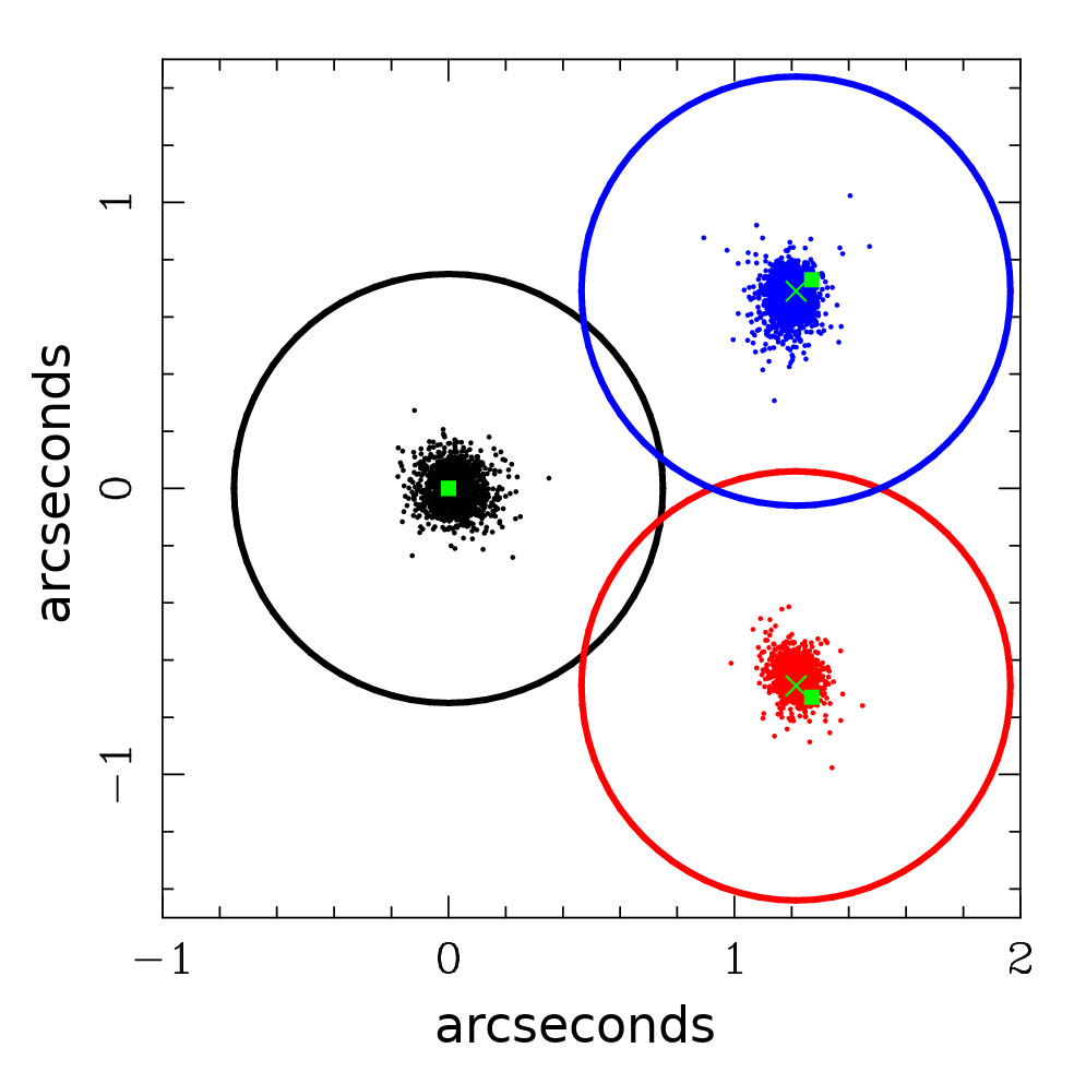
Throughout the years of HETDEX data acquisition, it has become apparent that there is a small difference between the commanded dithers and the actual dithers measured on sky. There is also a small dependence on Declination in this difference. Below is a graph showing the measured positions of the three dithers for HETDEX observations in HDR4:
As far as we can tell, this behavior has been consistent from ~2018 until at least 2023. The message to future VIRUS users is that there might be a small scale correction, of at most 4%, that could be applied. If your science goals require the relative dither centering to better than this, please consider applying a correction.
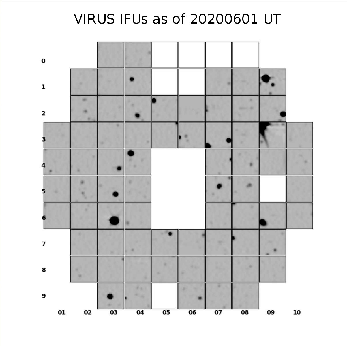
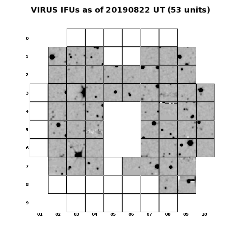
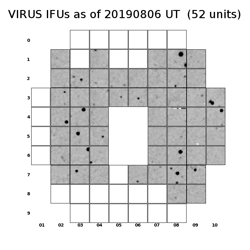
VIRUS IFU layout
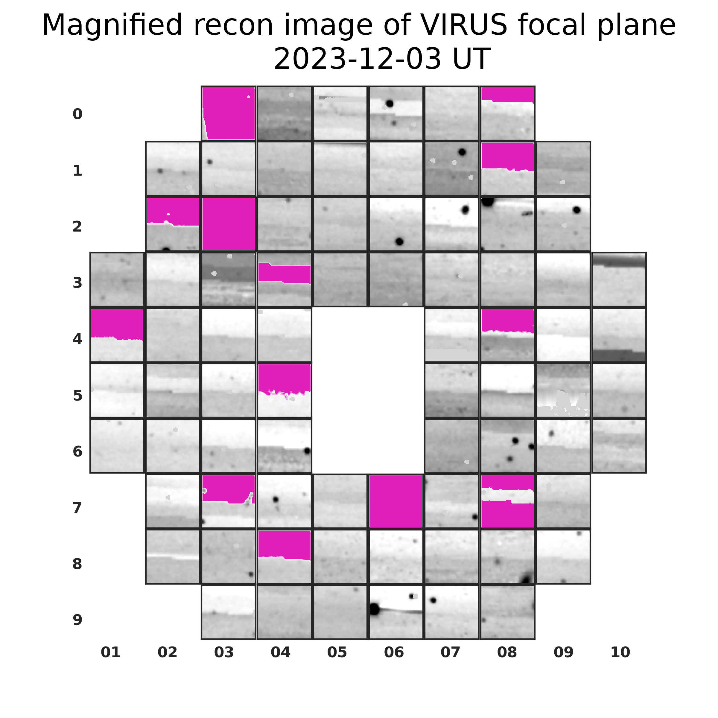
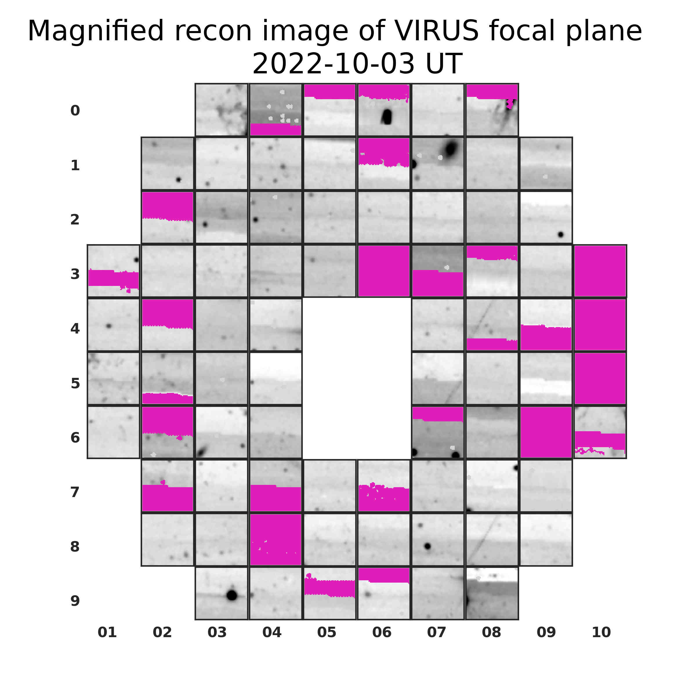
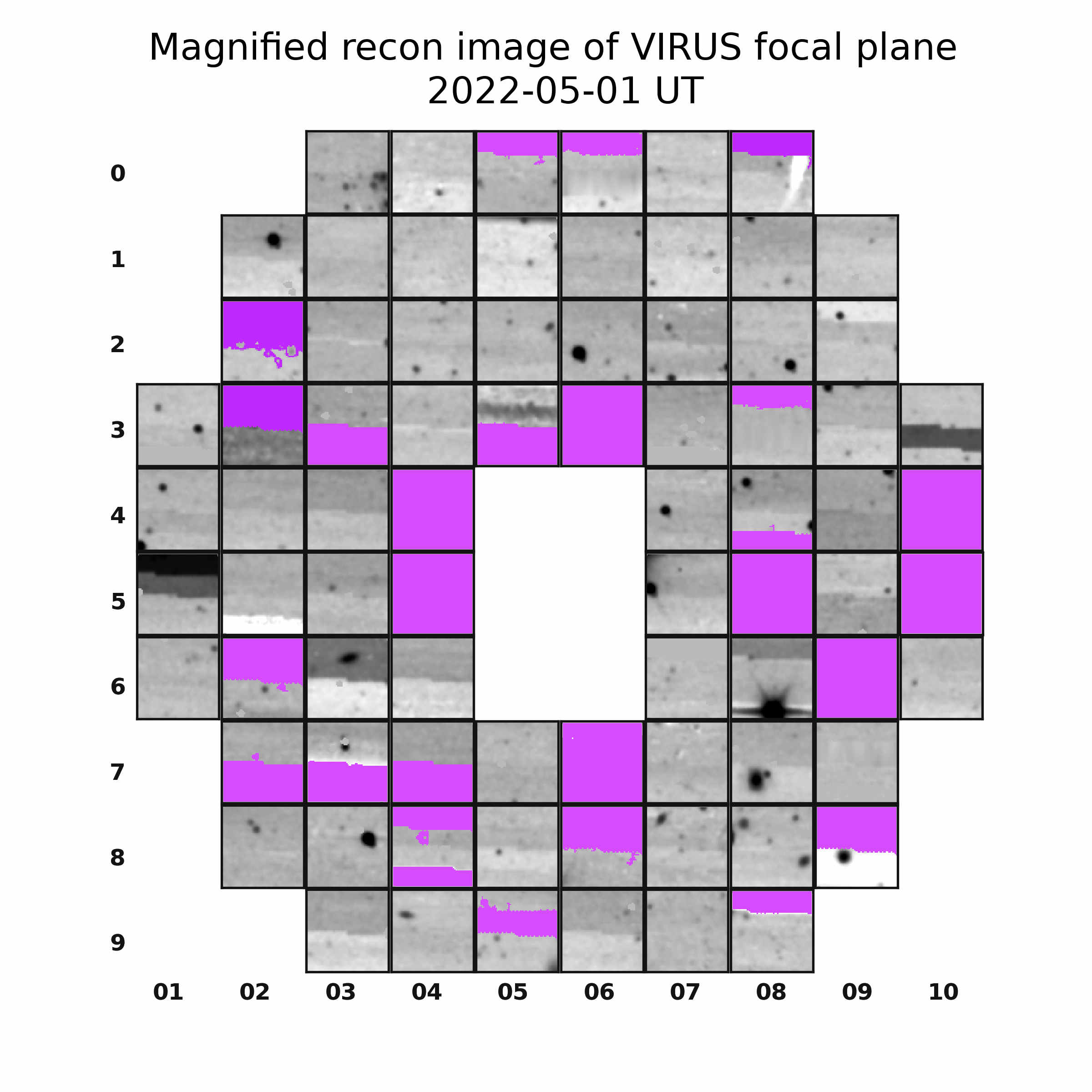
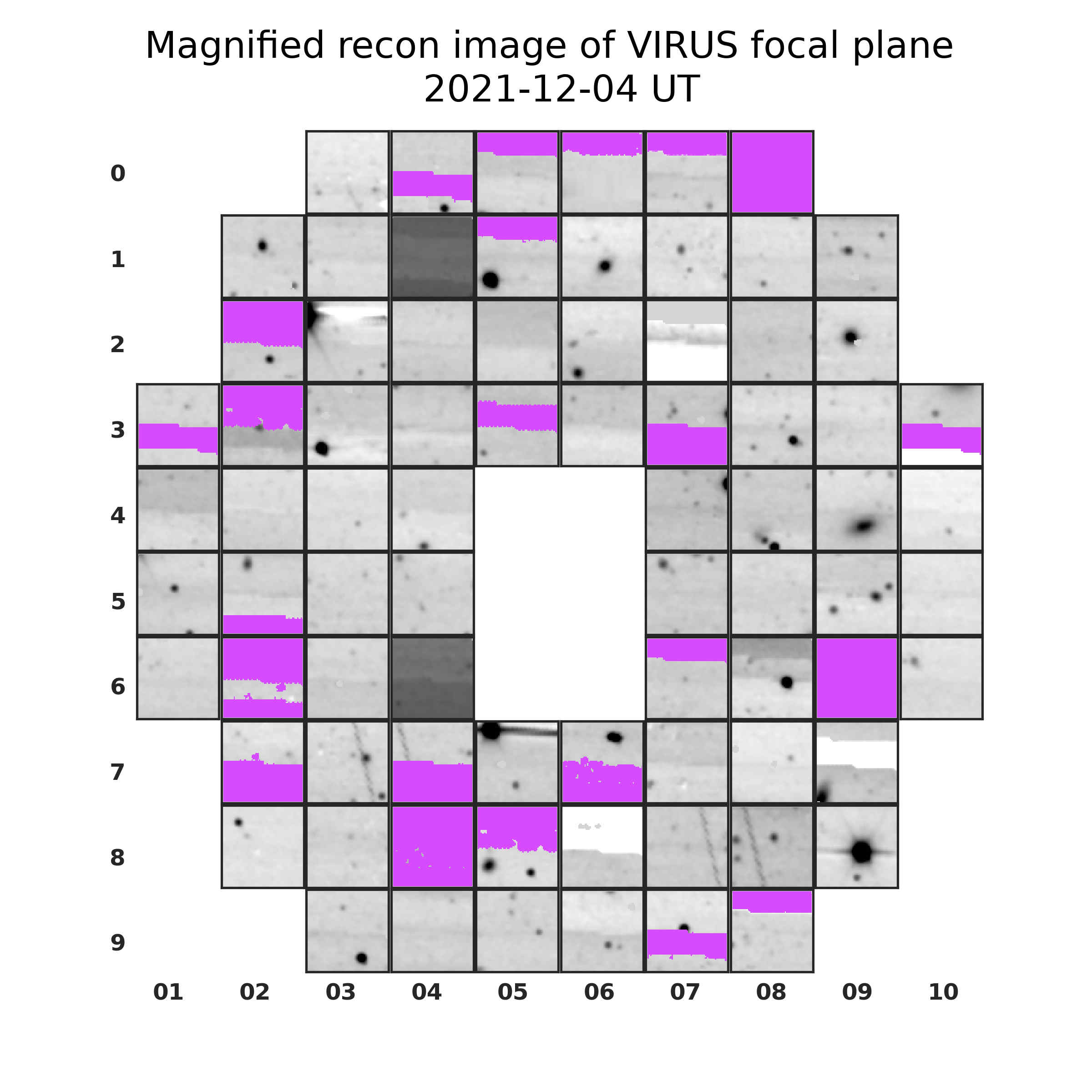
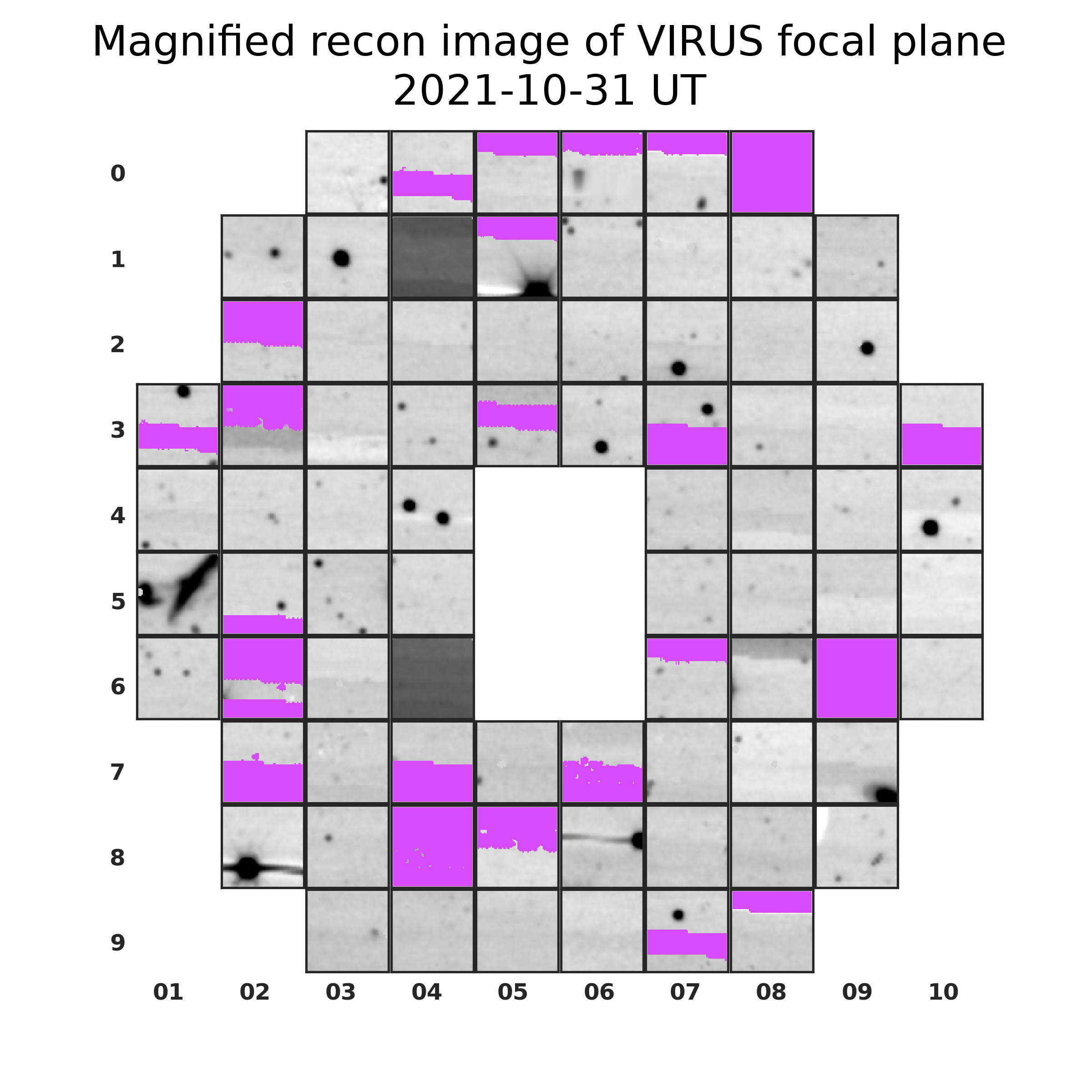
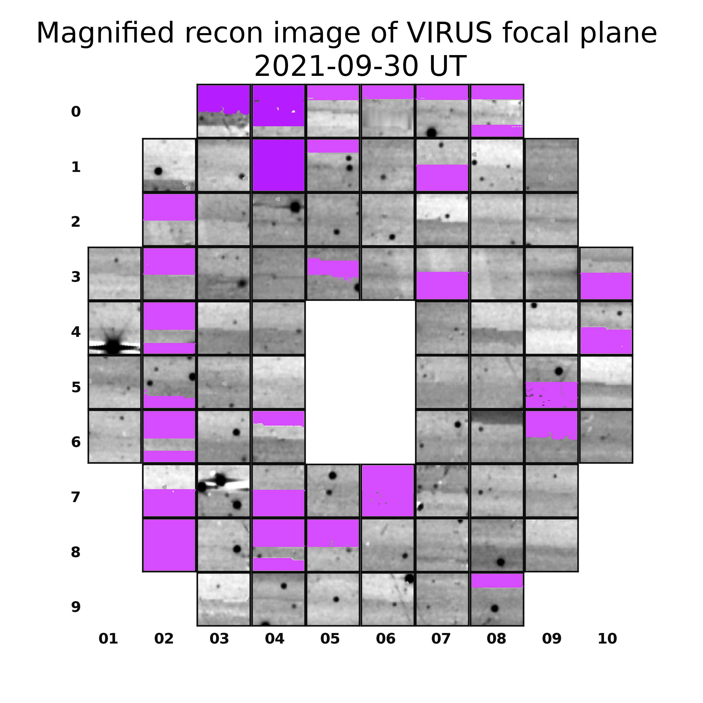
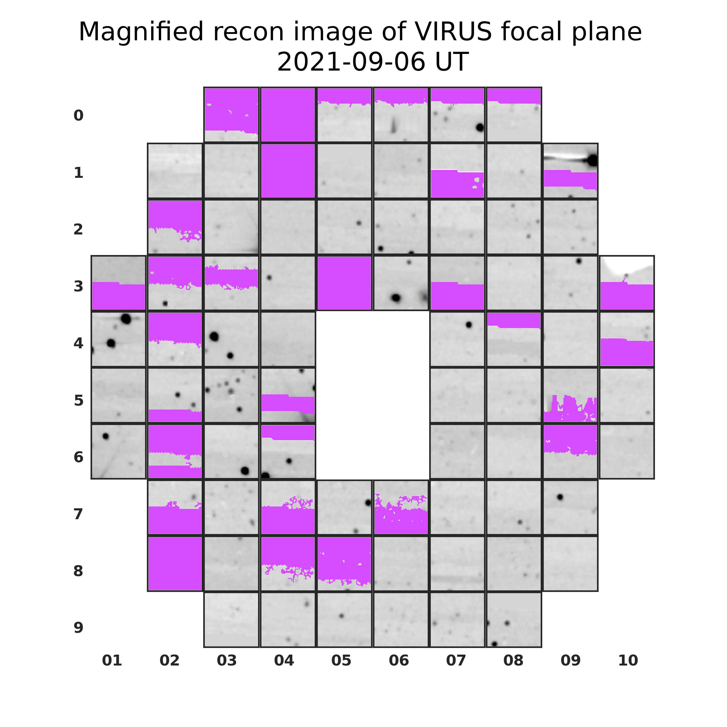
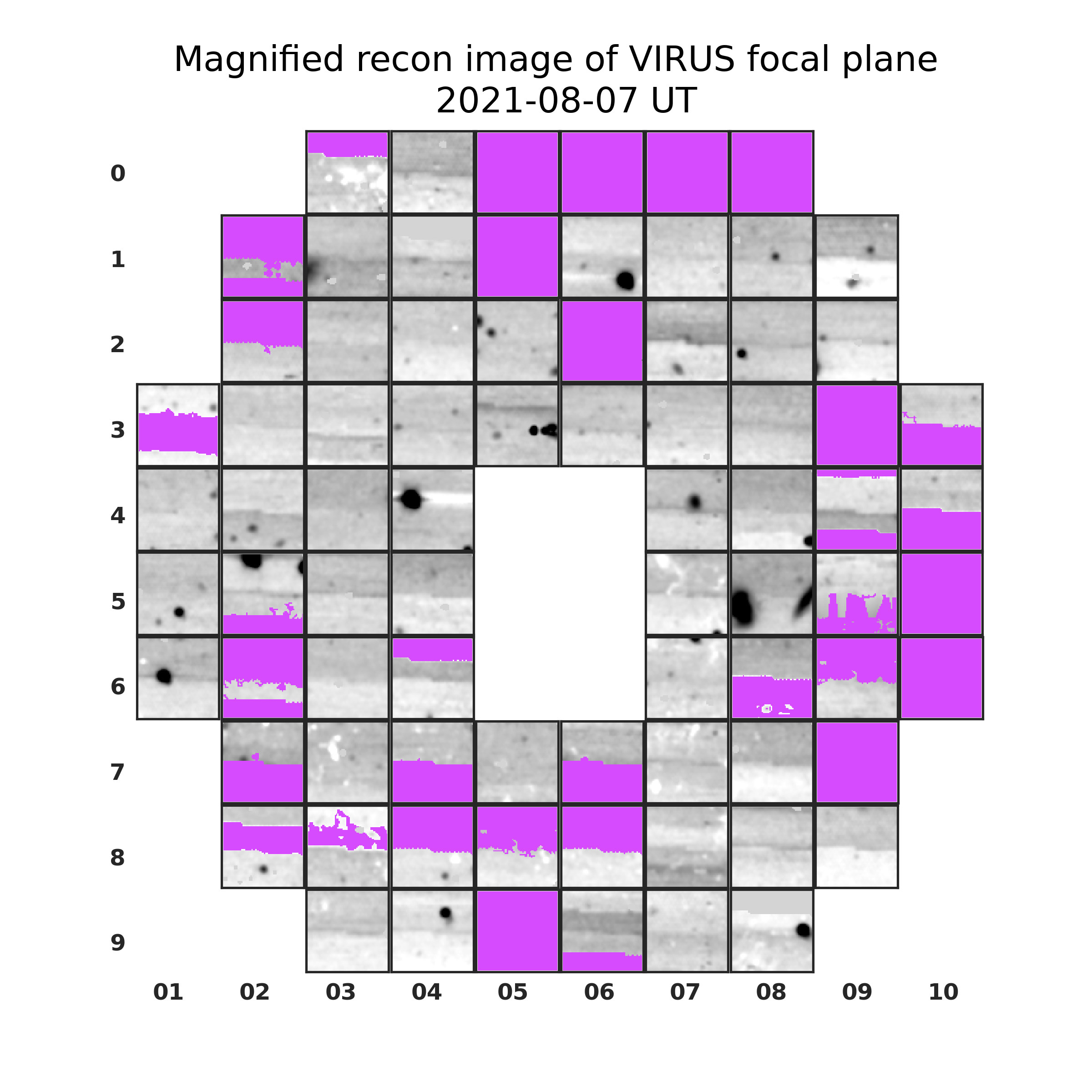
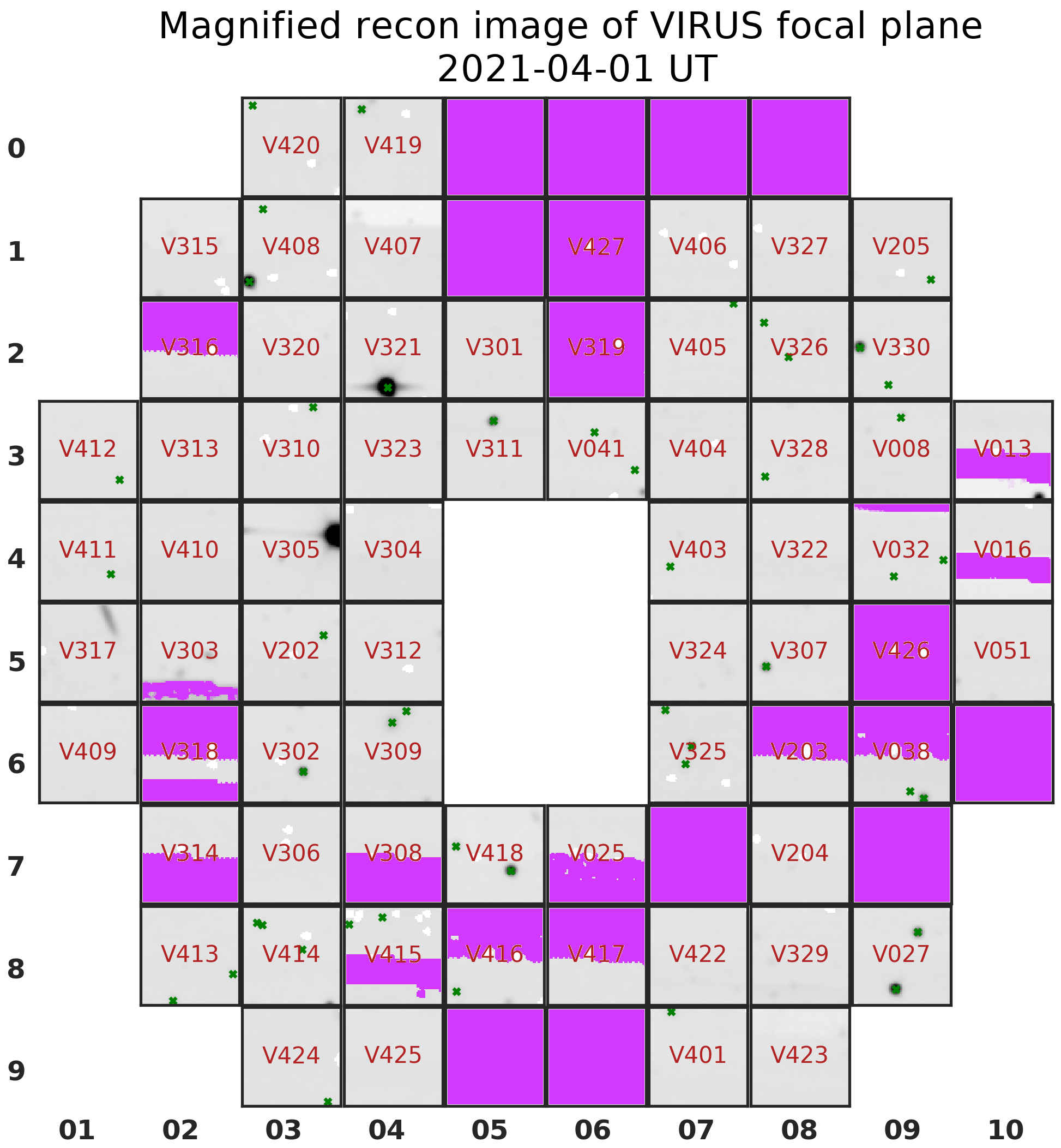
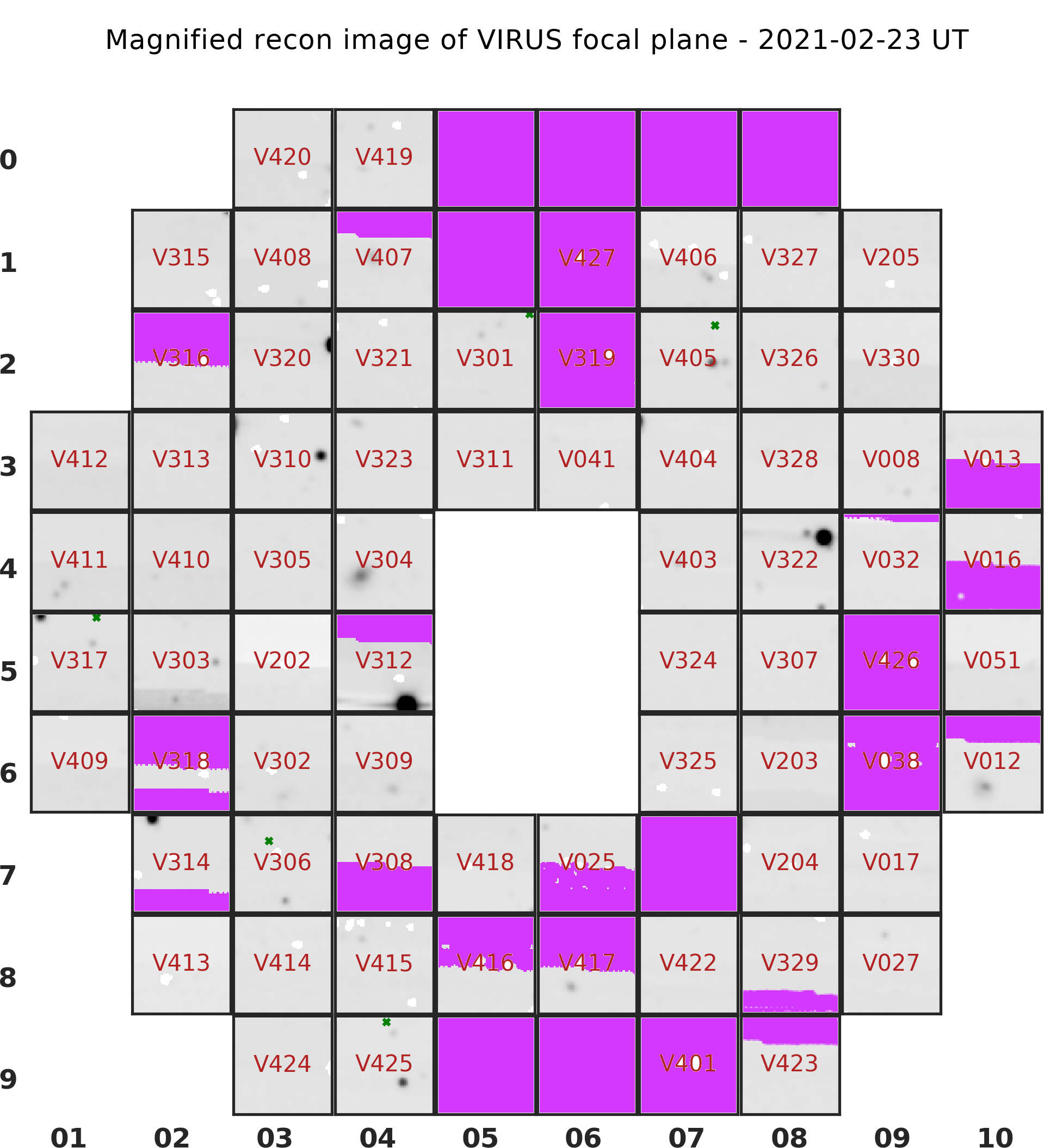
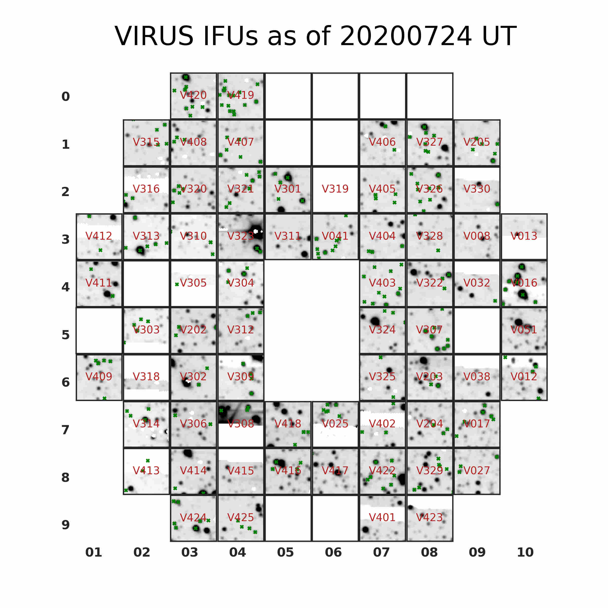
As new IFUs were brought to the telescope, the distribution of active fiber bundles was changing. Shown below is a (modified) view of the IFU distributions as of different dates. Note that the IFUs are NOT contiguous on the sky! The individual IFUs are magnified 2x here. If you need contiguous sky coverage, see the following information about tiling VIRUS observations. Magenta areas show bad amplifiers or IFUs without spectrographs attached.
How to place your target on a VIRUS IFU
The on-sky IFU positions are named using 3 digit code (2-digit COLUMN and 1-digit ROW), as indicated on the images above. For example the IFU in column 10 and row 3 would be IFU 103 and the IFU in column 2 and row 1 would be IFU 021. The center of the focal plane (referred to as the "IHMP") is referred to as IFU 000, and is the default position for VIRUS targets unless otherwise specified.
When you submit a TSL file in Phase II, you may specify the IFU which should be centered on your target. This is done using the TSL keyword VIFU, e.g., VIFU 046. You may want to consider the current status/quality of various IFUs before requesting observations with a specific unit -- see this page for more up-to-date details: http://www.as.utexas.edu/~gebhardt/virususe/virus_layout.html
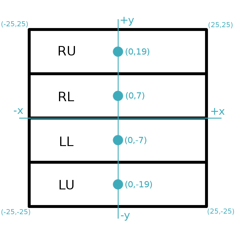
The CCD for each VIRUS IFU is read out by four separate amplifiers, which are arranged internally in quadrants (right-upper, right-lower, left-upper, left-lower), but correspond to rectangular regions on the sky, as shown below:
The x,y coordinate system (shown in blue) is in units of arcseconds, with its origin at the center of that IFU. When you request a given IFU, the default position is (0,7), or centered within the RL amplifier.
You can request a different offset position with the TSL keywords offsetx, offsety, which are given in arcseconds. For example, if you wanted to observe a star on the LL amplifier of IFU in slot 046, you would include these settings in your TSL file:
VIFU=046 OFFSETX=0 OFFSETY=7
Dithering and Tiling VIRUS observations
By default, VIRUS observations are taken in a 3-point dither pattern, moving approximately ~1.5" between each position. See the top of this page for an important warning about dithering! This dithering fills in the gaps between fibers in each IFU, but does not fill in the gaps between IFUs. If you want complete sky coverage, you must tile multiple dithered observations together to fill in the gaps between IFUs.
The most current and simplest approach to tiling VIRUS observations is explained in more detail here, using X & Y offsets (focal plane coordinates). The following notes describe a more manual and detailed approach to VIRUS tiling, which may be appropriate for advanced users.
If you are sure you need this level of detail, then keep reading...
It begins by requiring that you determine the parallactic angle(s) for the observations of your target. The focal plane is rotated to be aligned with the parallactic angle for each target, so the rotation relative to North will be different for each target. This angle will determine what offsets are required to tile multiple observations to fill in the gaps between IFUs (note that the parallactic angle will be different for a target observed on its Eastern track compared to its Western track).
If you have access to TACC and a modicum of bravery, you can run the "shuffle" code yourself to determine the parallactic angle(s) at which your target will be observed. Here are the basic steps (borrowed from one of Karl's webpages about VIRUS):
- Log in to TACC
- In an empty directory, run shuffle_config to generate config files
- Copy over the latest fplane file (ask if you don't know where to find it)
- run: do_shuffle -v RA DEC rad_off east/west IFU ra_offset dec_offset Name
- RA in decimal hours
- Dec in decimal degrees
- rad_off is not used, so use "0"
- east/west is 0 for east and 1 for west
- IFU is the position on the sky, like 046 or 000
- ra_offset,dec_offset are in arcsecond, relative to specified RA,Dec (probably both 0 for most applications)
- Name is a target name, used for output
- Locate and view the output file shout.result to get the RA,Dec of focal plane center and the Parallactic Angle (5th column in that file).
Once you have the Parallactic Angle, you can generate the positions of the 4 observations required to fully tile the sky. This style of tiling will suffice:
- nominal pointing (first position)
- offset +50" in the direction of the parallactic angle (second)
- offset +50" perpendicular to the parallactic angle (third)
- offset -50" in the direction of the parallactic angle (fourth)
When generating tiled VIRUS observations remember well that the East and West tracks will have different PAs and will require different positions to fully tile the sky. When you submit your TSL files for these observations you will want to specify an azimuth restriction of AZRES=E for East-only observations (or AZRES=W for West-only observations).
In case it is useful, you may consider using this tool to calculate the position angle of a target on sky given its declination.
Please contact your friendly Resident Astronomer if you have any questions and to verify that your target submission is correct: astronomer(at)het.as.utexas.edu
Last updated: Fri, 10 May 2024 20:10:20 +0000 sir

|
|
|